How to Wire Whole House Generator
How to wire whole house generator. Learn how to wire a whole house generator with ATS integration, panel connections, conductor sizing, grounding, and code
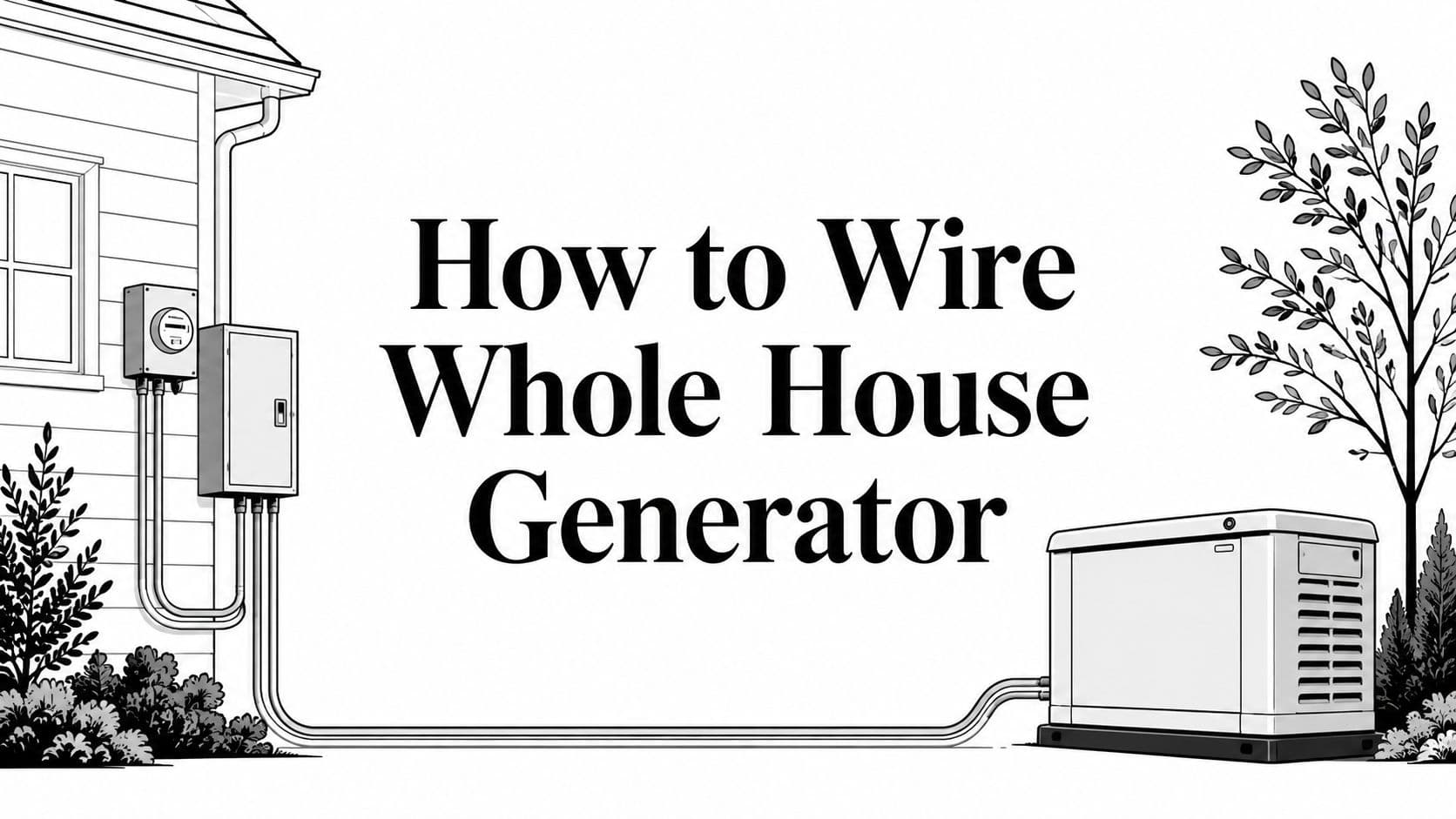
If you're staring at quotes, a generator brochure, and a panel in the garage, you're probably asking the same question every homeowner asks at this stage. What gets wired, what can wait, and what does the electrician need from you before anyone drills a hole or lands a conductor?
The answer isn't “hook the generator to the house.” A whole-house standby system is a power system design, with code rules, neutral strategy, permit documents, and load decisions that all have to line up before the first wire gets pulled. Once you understand the wiring logic, the rest of the project gets a lot less mysterious.
Table of Contents
- Planning the Wiring Job Before You Touch a Wire
- Understanding the Code Requirements That Shape Your Wiring
- Choosing the Right Transfer Switch Topology for Your Service
- Running Conductors and Landing the Transfer Equipment
- Grounding, Bonding, and Avoiding Neutral Conflicts
- Permits, Inspections, and Documentation That Pass Inspection
- Pre-Commissioning Checks and Common Field Errors
Planning the Wiring Job Before You Touch a Wire
A whole-house generator install starts with load thinking, not cable pulling. The biggest mistake homeowners make is assuming the electrician can “connect everything” after the generator arrives. In reality, the home's actual loads, the service size, and the transfer equipment all shape the wiring path.
Start with the loads, not the box
List the appliances and systems you want powered, then separate must-run loads from convenience loads. That split matters because standby systems are built around the premises load, while some projects need load shedding or managed circuits when the generator can't carry every device at once.
The service entrance also tells the electrician a lot before any work begins. A 100 A, 200 A, or 400 A service changes the transfer gear, conductor route, and available space around the meter and main panel. If the generator pad sits far from the service equipment, the wire path gets longer, and that affects conduit runs, trenching, and termination points.
Practical rule: the generator size, the transfer switch rating, and the house load need to be designed together, not chosen in separate conversations.
Decide what's DIY-realistic and what isn't
Some prep work is homeowner-friendly. Pad leveling, site access, and paperwork can often be handled before the electrician arrives, as long as you're following the installer's layout and local rules. Electrical terminations, line-side taps, final energization, and utility separation are licensed work, and they should stay that way.
Fuel type and placement also deserve an early decision. Natural gas, propane, and diesel each change the layout, and so do sound ordinances, setback limits, and clearances around doors, windows, and vents. If you want fewer surprises, hand the installer a complete packet: panel schedule, as-built service sketch, gas capacity chart, and the exact ATS model.
If you're still sizing the project, a good starting point is the generator sizing guide, because the wiring plan has to match the load plan.

Understanding the Code Requirements That Shape Your Wiring
A homeowner looking at a standby generator often sees one question first, where does the wiring start. Code answers that question before any conduit is bent or any conductor is landed. For most residential jobs, the starting point is NEC Article 702, which covers optional standby systems and points the installation toward listed transfer equipment instead of improvised backfeed methods.
Optional standby and legally required standby are not the same
Article 702 applies to optional standby systems. Article 701 covers legally required standby systems, and that classification changes the rules for source separation, signage, and routing. If the system is mislabeled on paper, the inspector can reject it even when the wiring looks clean.
Load handling comes next. The transfer switch, feeder, and generator output path need to be sized together, because a standby system is more like a matched set of parts than a pile of separate components. Load shedding is only acceptable when the system includes a listed means to do it.
A safe installation is not just powered. It is separated, listed, and sized for the load path you're building.
The code details that decide the layout
Transfer equipment has to be listed for the intended use under 702.7, and generator conductors are sized to carry 115% of the generator nameplate current according to NEC 702 guidance. If you want a broader permit overview alongside the code basics, the generator permits and codes guide is a useful companion. Those requirements shape the conductor path, the switching arrangement, and the way the service equipment is laid out.
The transfer device rating has to match the service and the installation method. A 200 A service often uses a 200 A-rated device when the switch sits between the meter and the main panel. That is not a cosmetic choice. It tells the installer how the source is separated and how the load path is protected.
Grounding and raceway rules also affect the layout, but they are handled under the NEC articles that apply during design and inspection. Local adoption still matters, so the code edition your jurisdiction enforces controls the permit and final sign-off.
| Requirement | Article 702 Optional | Article 701 Legally Required |
|---|---|---|
| System type | Optional standby loads | Legally required loads |
| Transfer equipment | Listed transfer equipment required | Listed transfer equipment required, with stricter source rules |
| Load handling | Full load or managed load shedding | Load handling tied to the required function |
| Signage and separation | Code-compliant separation required | More stringent separation and identification |
| Inspection focus | Safe standby operation | Critical continuity and compliance |
Choosing the Right Transfer Switch Topology for Your Service
The transfer switch topology decides how the neutral behaves, how the loads are isolated, and whether the generator is treated as a separately derived system. That's not a technicality. It changes the grounding strategy, the termination order, and the kinds of nuisance trips you'll chase later if the wiring is wrong.
Switched neutral versus non-switched neutral
A non-switched neutral keeps the neutral path continuous through the transfer gear. That setup is common in standard 120/240 V single-phase homes, and it simplifies bonding because the neutral stays tied to the service neutral path.
A switched neutral opens the neutral in the transfer process. When that happens, the generator is separately derived, and its neutral bond has to be handled differently so you don't create parallel neutral currents, nuisance GFCI or AFCI trips, or shock hazards as explained in independent generator guidance. The exact bonding approach has to match the topology, not the homeowner's preference.
Picking the pole count
The pole count tells you what gets switched. A 2-pole transfer switch is the common single-phase choice for hot conductors. A 3-pole setup switches L1, L2, and neutral, and a 4-pole setup is the typical three-phase answer when neutral switching is part of the design.
| Topology | Neutral Switching | Separately Derived System | Typical Use Case |
|---|---|---|---|
| 2-pole, non-switched neutral | No | No | Standard single-phase whole-house setup |
| 3-pole, switched neutral | Yes | Yes | Single-phase system needing neutral isolation |
| 4-pole, switched neutral | Yes | Yes | Three-phase installation with neutral switching |
Service-rated versus non-service-rated equipment matters too. If the gear is wired line-side of the main disconnect, it has to be service-rated. Interlock kits are only appropriate on non-service disconnect arrangements, and they still have to be listed for the exact panel model to satisfy inspection.
For a buyer-friendly comparison of transfer equipment types, the transfer switch installation guide is a useful companion while you're choosing topology.
Running Conductors and Landing the Transfer Equipment
Once the topology is set, the conductor path becomes a layout problem with code limits. The first check is the service equipment area, because you need enough clearance, a suitable fault-current context, and a location that supports the transfer switch or interlock hardware without crowding the meter or panel.
Size the conductors to the equipment, not to guesswork
Generator output conductors need to match the circuit design, and the ungrounded conductors are sized using the generator nameplate and the continuous-load rules tied to the output path. The practical field rule in the verified guidance is to use 115% of the generator nameplate current for the generator conductors per NEC 702 guidance. If the transfer switch is smaller than the service path or generator output, the wiring has to be revised before commissioning.
The conductor insulation and raceway choice also matter. The right insulation rating depends on the route, ambient temperature, and bundling conditions. Exterior runs need proper conduit sizing, and the transitions through walls or slabs should be planned before anyone lands a lug.
If the neutral strategy isn't settled first, conductor landing gets messy fast. That's why the switch topology comes before the wire pull, not after it.
Landing points and workmanship details
At the transfer equipment, each conductor lands on the correct terminal set, utility on normal, generator on emergency. Every connection should be torqued to the manufacturer's value with a calibrated wrench, because loose lugs create heat and hard-to-find failures. Labeling both ends of every conductor helps the inspector and the commissioning tech verify that the path matches the drawing.
Don't mix control wiring and power wiring in the same careless bundle. Keep the generator conductors separated from sensitive low-voltage runs, use anti-short bushings in metal raceways, and confirm phase relationship before energizing the system. On a selected-circuit installation, the same discipline still applies, even if the generator doesn't feed every breaker in the house.
| Generator kW | Amps @ 240V | Ungrounded Conductor | Neutral where required | Equipment Ground |
|---|---|---|---|---|
| 10 | 41.7 | Sized to the generator output path | Sized per the switch topology | Sized per equipment grounding rules |
| 14 | 58.3 | Sized to the generator output path | Sized per the switch topology | Sized per equipment grounding rules |
| 18 | 75.0 | Sized to the generator output path | Sized per the switch topology | Sized per equipment grounding rules |
| 20 | 83.3 | Sized to the generator output path | Sized per the switch topology | Sized per equipment grounding rules |
Grounding, Bonding, and Avoiding Neutral Conflicts
This is the part that trips up a lot of otherwise clean installs. Grounding and bonding are not the same thing, and if they're treated like one problem, the generator can create a parallel return path that shows up later as nuisance tripping or unexplained faults.
Match the grounding path to the topology
The grounding electrode conductor should run from the transfer switch grounding bar to the existing grounding electrode system, and it should stay continuous and properly sized from the largest ungrounded conductor. That creates the fault-clearing path without using the equipment grounding conductor as a current-carrying neutral substitute.
If the transfer switch has a switched neutral, the generator is separately derived, so the neutral is isolated in that configuration. If the setup uses a non-switched neutral, the service neutral remains the reference path, and the existing bond at the main service equipment stays in control. The mistake is trying to keep both bonding schemes alive at once.
Keep breaker behavior predictable
GFCI and AFCI breakers are sensitive to bad neutral paths, especially where shared neutrals or parallel returns exist. That's why neutral/ground confusion often shows up as nuisance trips before anyone notices a visible wiring fault. The fix is not to swap breakers blindly, it's to correct the bond and topology that created the problem.
Detached structures and subpanels deserve the same scrutiny. If a second electrode system or downstream bond creates objectionable current, the generator installation stops behaving like a single coordinated system. The safest field habit is simple, isolate neutrals where required, bond only where the design calls for it, and never let the grounding conductor carry normal load current.
Permits, Inspections, and Documentation That Pass Inspection
A generator project can be wired correctly and still fail if the paperwork does not match the installation. The permit path is part of the job, because inspectors treat the electrical work, the fuel work, and sometimes the placement or zoning details as separate approvals.
Build the permit package before the crew mobilizes
A generator connection to a home panel requires an electrical permit, and the fuel line often needs its own gas or mechanical approval. One permit guide also notes that interlock kits have to be listed for the exact panel model to pass inspection, which is why “close enough” panels and generic kits create problems late in the process as outlined in the permit guide.
That same jurisdictional guidance asks applicants to show generator kW, transfer-switch amperage, and subpanel size on the permit application. A clean one-line diagram should show the service entrance, transfer equipment, overcurrent protection, conductor sizes, grounding electrode connection, and any subpanels. If the load calculation is weak, the reviewer may decide the generator cannot support the connected standby loads.
What inspectors look for
The equipment documentation needs to match the field installation. The transfer switch listing, generator listing, manufacturer instructions, and any anchoring details need to be available on site. Rough-in inspection usually happens before the system is energized, and final approval comes only after the electrical, and sometimes fuel, inspection is complete.
Keep torque logs, test results, and approved drawings together. Those records help with warranty questions, future service calls, and insurance documentation if anyone ever asks how the system was installed. When the paperwork is missing, even a good install gets harder to defend.
Pre-Commissioning Checks and Common Field Errors
Commissioning day tells the truth. A system can look perfect on paper and still fail if the pad is off, the fuel feed is weak, or the transfer gear isn't behaving under load.
The checks that matter before first long run
Confirm the pad is level to the manufacturer's tolerance, then verify fuel pressure at the generator inlet. Run the transfer switch through a full exercise cycle under realistic startup conditions, not just a no-load click test. The system should physically prevent utility and generator from being on at the same time, and that safety behavior needs to be proven before the homeowner depends on it.
A few field errors show up again and again. Independent guidance identifies unlevel pads, undersized motor-starting capacity, and neutral bonding mistakes as the common trouble spots in generator installs per field installation guidance. Those issues aren't abstract, they turn into nuisance trips, voltage dips, and commissioning delays fast.
Commissioning rule: don't call a system complete until it has carried load, stayed cool at the terminations, and passed the source-separation check.
What to watch during the first run
If a motor load pulls voltage down too hard, the ATS can interpret it as a fault and switch behavior becomes unreliable. If the neutral-ground bond is wrong downstream of the transfer equipment, GFCI devices start complaining and fault tracing gets ugly. On three-phase systems, reversed rotation can damage motors even when the lights all come on.
Use a simple pass list. Torque marks should still line up, conductor temperatures should stay stable after a realistic run, and breaker self-tests should pass without nuisance trips. When those checks are clean, you're looking at verified behavior, not just a tidy installation.
If you want help narrowing the installer search before you start calling around, GeneratorInstallerList organizes standby and whole-house generator installers by signal, location, and service focus. It's a practical starting point when you're comparing quotes, checking who handles transfer-switch wiring, and lining up a crew that can take the project from permit to final inspection.
- whole house generator wiring
- automatic transfer switch
- generator conductor sizing
- NEC 702 standby generator
- generator grounding and bonding
Ready to find who to call?
Open your state page or search by ZIP for a distance-sorted list.