Whole House Generator Transfer Switch Guide
Learn how a whole house generator transfer switch works, the types to choose from, sizing rules, code requirements, and what to plan before installation.
You wake to a winter storm, and the house has gone quiet. The lights flicker out, the furnace stops, the refrigerator loses power, and somewhere outside, a standby generator begins to hum. For that generator to energize the home safely, one device has to control the handoff between the utility and the backup source.
That device is the whole house generator transfer switch. It isn't a larger breaker or an accessory you choose after selecting the generator. It determines which circuits receive backup power, how much load the generator must support, how the service equipment is arranged, and which permits and inspections the project will require. A good installation starts with those decisions, not with a brand name.
Table of Contents
- When the Power Goes Out and the Generator Kicks In
- What a Whole House Generator Transfer Switch Does
- The Main Transfer Switch Types Homeowners Choose Between
- Sizing the Transfer Switch to Your Service and Loads
- Code and Safety Standards That Shape Your Project
- Why Whole House Rarely Means Every Appliance at Once
- Permits, Placement, and Inspection in Plain English
- A Clear Checklist Before You Talk to an Installer
When the Power Goes Out and the Generator Kicks In
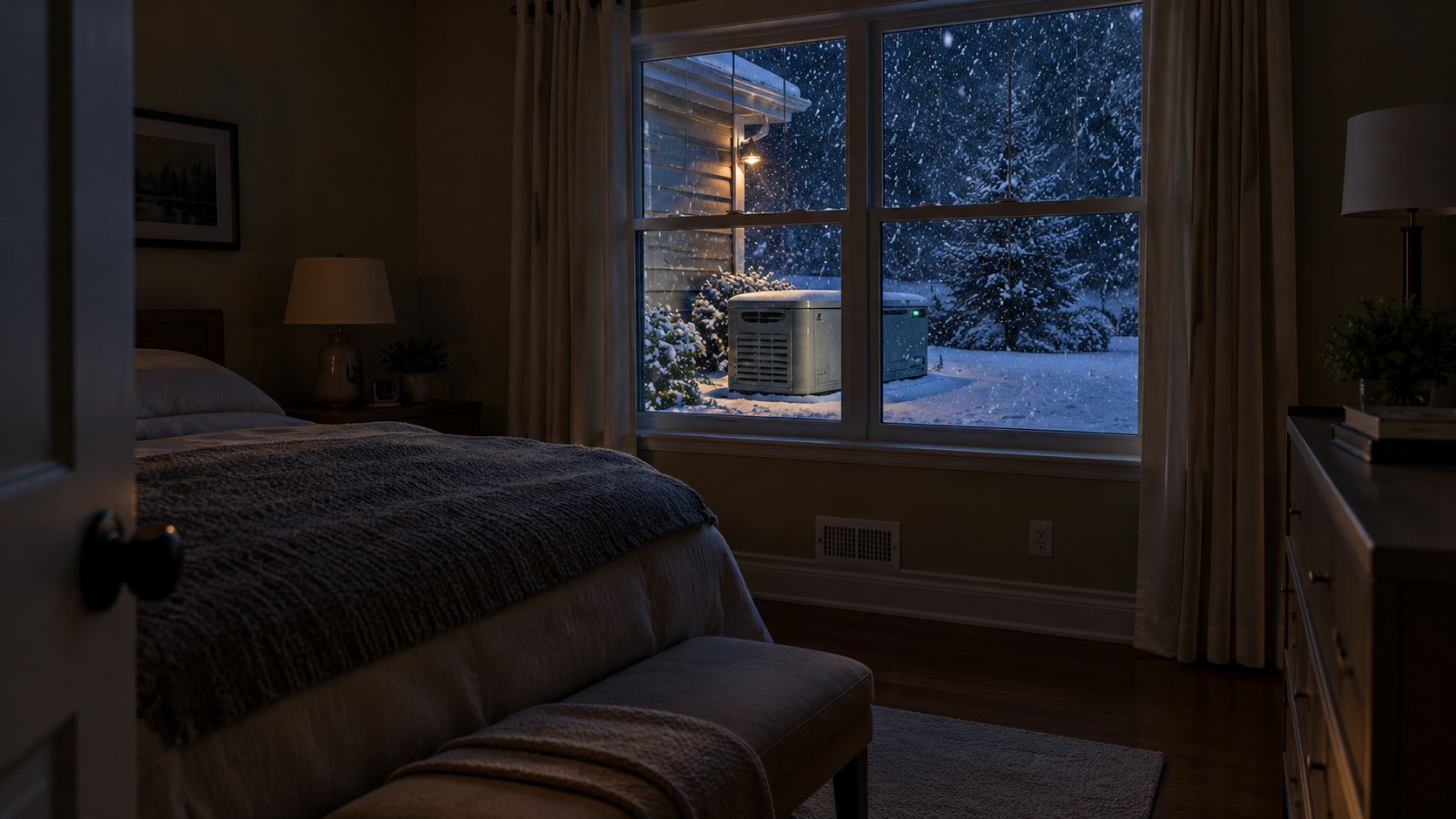
Snow covers the windows, the bedroom light stays dark, and the furnace and sump pump stop. Outside, the standby generator starts. Its engine can produce backup power, but a separate device must decide whether that power is allowed into the home.
The transfer switch controls that handoff. It disconnects the house from the utility before connecting an approved generator source to the panel. Once utility service returns, it opens the generator connection and restores the utility path, keeping the two sources separated.
The safety decision happens at the service equipment
Utility conductors and generator conductors cannot energize the same premises wiring at the same time. Otherwise, generator current could flow backward through the service drop toward utility lines that workers believe are de-energized. That condition is called backfeed.
A listed transfer switch prevents the sources from being connected together. It also separates the generator from abnormal utility conditions that could harm the generator or its controls. In practical terms, the switch is the safety connection between the outdoor generator, the main service equipment, and the circuits inside the house.
Practical rule: If a generator will connect to premises wiring, plan the transfer equipment before planning the generator connection.
Modern code practice requires transfer equipment when a generator connects to premises wiring. NEC Article 702 guidance for generator transfer switches describes a transfer switch or listed mechanical interlock as the method for preventing simultaneous utility and generator connection.
Automatic comfort depends on correct switching
An automatic transfer switch monitors utility power, signals the standby generator to start, and moves the approved load to the generator without requiring someone to operate the panel during a storm. A manual transfer switch requires the homeowner to start or connect the generator and operate the switch.
The project decision is broader than automatic versus manual operation. A selected-circuit setup may keep only chosen loads running, while a true whole-house automatic transfer switch can serve the broader service. In a modern home with electric heating, cooking, water heating, vehicle charging, or other large loads, that choice affects generator capacity, load management, equipment arrangement, permits, and inspection. The transfer switch is therefore both a hardware choice and a plan for how the home uses power during an outage.
What a Whole House Generator Transfer Switch Does
The transfer switch controls which source supplies the home. It allows utility power or generator power to feed the panel, while preventing both sources from connecting at the same time. The equipment is therefore part of the electrical safety plan, not a box placed beside the generator.
Its contacts, controls, interlocking, and protective design manage the changeover under defined electrical conditions. The switch itself does not generate electricity. It provides the controlled handoff between the utility and the generator.
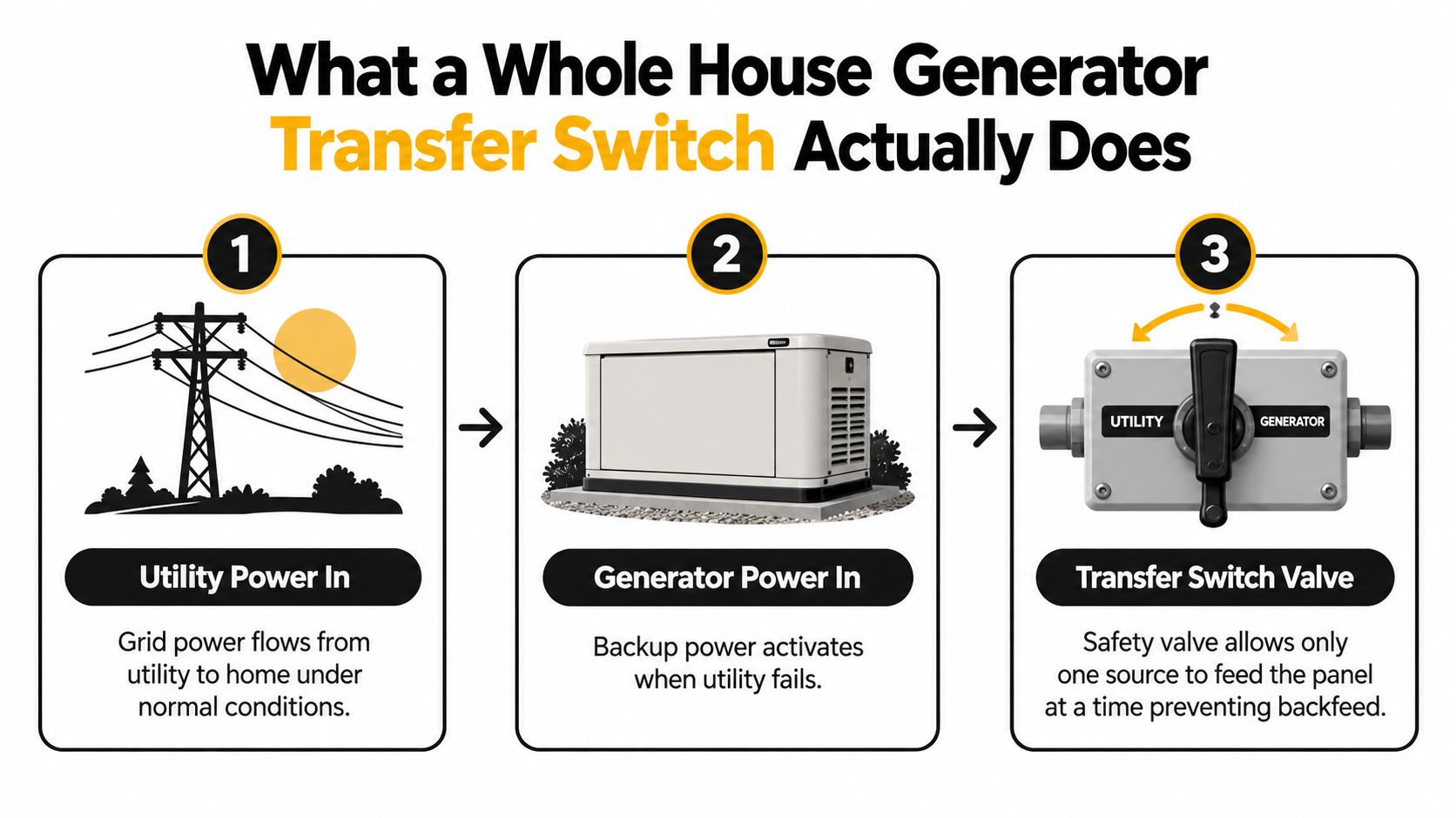
The three operating stages
Utility power supplies the home. During normal operation, the transfer equipment keeps the generator disconnected while utility power feeds either the service or the selected backup circuits.
The generator becomes available. During an outage, an automatic system detects the loss of utility power and starts the generator. A manual system waits for the homeowner to start or connect the generator and operate the equipment.
The switch transfers the approved load. The switch opens the utility path before closing the generator path. This break-before-make sequence prevents the two sources from being paralleled.
The transferred load depends on the project design. A service-rated whole-house unit sits in the main service path and can transfer the service conductors. A selected-circuit arrangement sends power only to circuits moved to a backup panel or protected section of the existing panel. That distinction becomes important in homes with electric heating, cooking, water heating, vehicle charging, or other large loads.
The switch must match the conductors, overcurrent protection, fault conditions, enclosure, and intended use. UL 1008 transfer switch requirements and ratings covers transfer equipment for emergency and standby applications, including continuous current and Withstand and Closing Rating requirements.
For a visual explanation of the handoff, this short video shows the basic transfer sequence:
Any generator connected through the home's existing wiring needs a safe means of transfer. The device may be automatic, manual, service-rated, or selected-circuit, but a loose extension-cord arrangement cannot replace listed transfer equipment. That choice also affects load management, permitting, equipment placement, and inspection.
The Main Transfer Switch Types Homeowners Choose Between
Homeowners usually encounter four configurations in quotes. They overlap in some product catalogs, so ask the installer where the switch sits and which conductors it transfers, not just what the salesperson calls it.
| Switch Type | Switching Action | Typical Generator Size | Best Fit |
|---|---|---|---|
| Manual transfer switch | Homeowner operates the switch | Portable or modest backup generator | Essential circuits and hands-on operation |
| Automatic transfer switch | Detects utility loss and transfers automatically | Standby generator matched to selected or calculated loads | Homes that need unattended backup |
| Service-rated switch | Transfers the service path near the main disconnect | Generator sized for the calculated transferred load | Broad whole-house coverage |
| Selected-circuit switch | Transfers only designated circuits | Generator sized for priority loads | Homes using load priorities or a smaller generator |
Manual transfer for deliberate, limited backup
A manual transfer switch often pairs with a portable generator and a short list of essential circuits. You might choose refrigeration, lighting, a furnace blower, a sump pump, or a communications circuit, depending on the home's wiring and the generator's capacity.
The tradeoff is involvement. You must get the generator into position, connect it as designed, start it, and operate the transfer equipment. That can work well for an owner who wants lower system complexity and doesn't mind managing an outage.
Automatic transfer for unattended operation
An automatic transfer switch monitors the utility and controls the standby generator's start and stop sequence. It suits homeowners who may be away, who want the furnace or refrigeration restored without manual action, or who don't want to handle equipment outdoors in severe weather.
Automation doesn't eliminate sizing decisions. The generator still has to support the calculated transferred load, unless an approved load-management system sheds nonessential demand.
Service-rated versus selected-circuit
A service-rated ATS generally sits in the service path and may function as the service disconnect. It can provide a clean whole-house arrangement, but the generator, fuel supply, conductors, and protective equipment must support the load the system is designed to transfer.
A selected-circuit ATS limits backup to chosen loads. That can make sense in a home with electric heat, an EV charger, an induction range, or other large loads that shouldn't all start together. The installer can prioritize daily necessities instead of treating every breaker as equally important.
The cost and convenience difference comes from the complete project, not the switch alone. A larger service-rated design may require more generator capacity and fuel infrastructure, while a selected-circuit design may require a critical-loads subpanel or circuit relocation. Ask for both options when the household's actual outage priorities are clear.
Sizing the Transfer Switch to Your Service and Loads
A transfer switch isn't sized only by the generator's advertised output. For a whole-house installation, the switch is normally matched to the home's service disconnect or main-panel rating, while the generator is selected against the calculated load that the system will transfer.
Consider a 200 A residential service. A whole-house setup will generally use a 200 A service-rated ATS because the switch is carrying the service path, even if the generator can't produce 200 A continuously. The generator's output and the home's calculated demand are separate parts of the design.
| Variable | Typical 200 A Value | Effect on Switch Choice |
|---|---|---|
| Residential service rating | 200 A | Points toward a 200 A service-rated ATS for whole-house transfer |
| Generator output | Must be established by load calculation | Determines how much demand can operate without overload |
| Transferred load | Full calculated load or selected circuits | Determines whether load management is necessary |
| Available fault current | Must be confirmed at the installation | Must fall within the switch's tested WCR |
| Service location | Main service equipment or selected-load panel | Influences enclosure, conductor routing, and equipment arrangement |
Separate the service rating from generator capacity
A 200 A ATS doesn't mean the generator can run every appliance at full demand. It means the transfer equipment is suitable for the service path, subject to its listing, installation conditions, and protective-device coordination. If the generator is smaller than the possible connected load, the design needs a calculated operating plan.
That plan may use selected circuits, automatic load shedding, or both. A furnace and refrigerator could receive priority while an EV charger, electric dryer, or other nonessential load is disconnected when the generator approaches its limit.
The generator sizing guide can help you organize the load discussion before an electrician performs the formal calculation. It shouldn't replace the installer's review of the panel schedule, motor starting demands, service equipment, and local requirements.
Read the nameplate, not just the ampere number
The installer should verify the ATS continuous current rating, voltage and phase configuration, pole arrangement, enclosure rating, service rating, and WCR. UL 1008 equipment uses a Withstand and Closing Rating to identify the prospective fault current the device can safely withstand and close onto under specified test conditions. This technical overview of ATS ratings also describes the evolution of UL 1008 and notes minimum automatic transfer switch life expectations of 3,000 to 6,000 operations.
Available fault current comes from the upstream electrical system and protective devices, not from the generator's normal running output. A switch with adequate ampacity but inadequate WCR can still be the wrong device.
The correct question is not “How many amps does the switch handle?” It is “Is this exact switch listed for this service, load, fault level, and installation method?”
Service-rated disconnects and cable assemblies also affect the design. The electrician may use a service-rated ATS to replace or incorporate the main disconnect, keep the service path orderly, and reduce unnecessary conductor changes. That arrangement must be confirmed from the equipment listing and the authority having jurisdiction.
Code and Safety Standards That Shape Your Project
The code conversation becomes easier when you separate three layers. NEC Article 702 governs optional standby systems, UL 1008 addresses the transfer equipment itself, and the local authority having jurisdiction, or AHJ, enforces the adopted code and local amendments.
NEC-based guidance requires a transfer switch or listed mechanical interlock when a generator connects to premises wiring. For a whole-house automatic system, the ATS must be sized to carry the full calculated load being transferred, or the design must use automatic load management to remove selected demand. This plain-language NEC 702 guide explains why service-rated transfer equipment is often matched to the home's service rating.
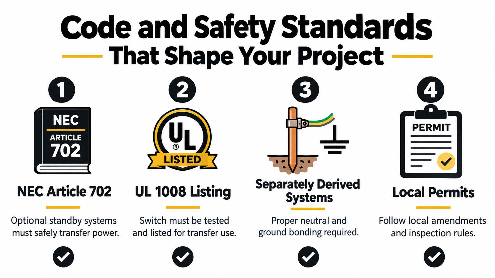
What the installer should verify
Listing and application: The switch should be listed for transfer use and appropriate for the emergency or standby application.
Current and fault ratings: The continuous current rating must suit the served load, while the WCR must cover the available fault current under the installation's protective-device arrangement.
Neutral and grounding arrangement: The installer must determine whether the generator is a separately derived system and handle the neutral and bonding conductors accordingly. Don't accept a generic statement that the neutral is always switched or never switched. The system configuration decides.
Overcurrent protection: Breakers, fuses, service disconnects, and generator conductors must coordinate on both sides of the transfer equipment.
Documentation: A load calculation, one-line diagram, equipment cut sheets, grounding details, and site information give the inspector something specific to review.
UL 1008 began in 1972 and became an American National Standard in 1976. Its scope includes automatic, manual, closed-transition, and other transfer equipment up to 1000 volts, with later editions adding testing and coverage changes. Those details matter because a transfer switch is a tested safety device, not a field-built shortcut.
The AHJ may request an electrical permit, a separate gas or mechanical permit, and an inspection before the system is energized. Local rules can also govern generator placement, service access, noise, fuel connections, and utility coordination. The installer should identify those requirements before ordering equipment.
Why Whole House Rarely Means Every Appliance at Once
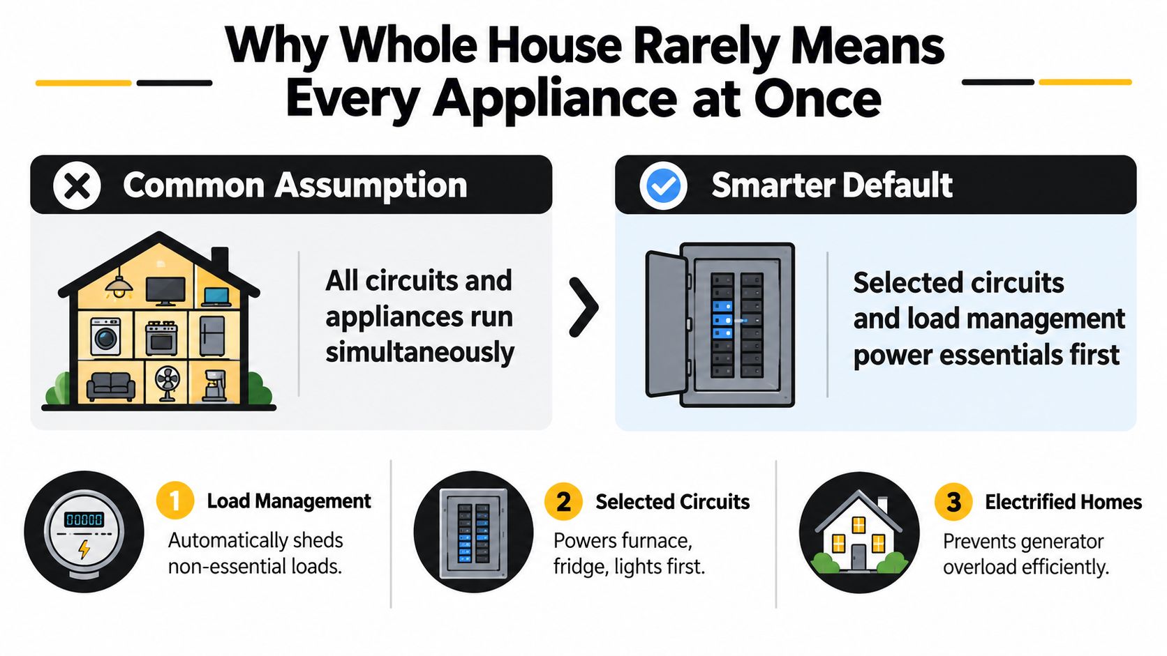
“Whole house” sounds like unlimited power, but it usually describes where the system can send power, not how much power every appliance can consume simultaneously. A service-rated ATS may energize the home's whole panel, while the generator still needs a strategy for competing loads.
This distinction is especially important in an electrified home. A heat pump can demand substantial starting power, an induction range may run while a dryer is heating, and an EV charger can add a sustained load. A well pump, air conditioner, or electric water heater can create another starting or running demand just when the generator is already carrying the house.
The practical difference between coverage and capacity
A true whole-house arrangement can keep the service energized, but the generator must still operate within its output limits. If the calculated transferred load exceeds that output, the installation needs load management or a narrower backup plan.
A selected-circuit system takes a more direct approach. The electrician moves or protects the circuits that matter most, such as:
- Heating and refrigeration: Furnace controls, blower equipment, refrigerator, and freezer.
- Water and drainage: Sump pump, well pump, or sewage ejector where applicable.
- Essential lighting and communications: Selected lighting circuits, internet equipment, and security devices.
- Comfort and convenience: A heat pump or cooking circuit only if the generator and controls can support it.
Loads such as an EV charger, electric dryer, pool heater, or second air-conditioning system may be left off or assigned a lower priority. The correct list depends on the home, climate, equipment, and the owner's tolerance for manual restrictions.
Load management changes the design conversation
Automatic load-management modules monitor generator demand and shed designated loads when priority equipment needs the available capacity. Once the generator has room, the controls may restore those loads according to the system's programming and the equipment manufacturer's instructions.
This approach can avoid treating the largest possible connected load as the generator's required continuous output. It doesn't make an undersized generator safe by itself. The electrician still has to verify compatibility, motor-starting behavior, control wiring, breaker arrangements, and the sequence that the equipment is listed to perform.
A whole-house panel can be convenient without being an invitation to run every high-demand appliance together.
For many modern homes, the better design question is: Which loads must operate together, and which loads can wait? That answer often produces a more honest generator and transfer-switch specification than the phrase “whole house” alone.
Permits, Placement, and Inspection in Plain English
A transfer switch installation is permanent electrical work. Many jurisdictions require an electrical permit, and a standby generator connected to natural gas or propane may also require a gas or mechanical permit. Local checklists can request load calculations, one-line diagrams, equipment information, placement drawings, and setback documentation, as described in this generator permits and codes guide.
A typical project sequence
The installing contractor usually starts by reviewing the service, proposed generator, fuel source, transfer equipment, and site. The contractor then prepares the permit package and identifies whether the utility must coordinate a meter disconnect, service interruption, or other approval before the work can be energized.
After approval, the crew installs the generator base, fuel piping, electrical raceways, transfer switch, grounding and bonding components, and control wiring. Rough inspections may occur before equipment is closed up, followed by final electrical and gas inspections. The system should be tested after approval so the homeowner knows the generator starts, transfers, carries the intended priority loads, and retransfers correctly.
Exterior placement creates avoidable delays
The generator needs a stable outdoor base, safe exhaust direction, service access, and enough space from openings and property lines. Local rules can be stricter than the general guidance a manufacturer prints in its installation manual, so the AHJ and utility requirements control the final location.
Common friction points include:
- Property and zoning limits: The proposed pad may not satisfy local property-line or access rules.
- Windows and doors: Exhaust and combustion-air clearances can rule out a convenient wall location.
- Fuel infrastructure: Natural-gas capacity, propane tank placement, trenching, and burial depth can change the scope.
- Neighborhood restrictions: Historic districts, HOA design review, and dense lots may require an alternate placement.
- Weather and ground conditions: Frozen soil and difficult excavation can complicate fuel and conduit work.
Inside the home, the ATS is usually installed near the main service equipment or the selected-load panel. Shorter conductor runs can simplify routing, but the switch still needs working clearance and must remain accessible for inspection and service.
Don't energize the system because the generator starts successfully. The installation needs the required permits, completed inspections, utility coordination, and documented transfer test.
A Clear Checklist Before You Talk to an Installer
Bring a written list to the quote visit. It gives the electrician the information needed to compare a service-rated whole-house design with a selected-circuit or manual arrangement.
Electrical information
- Service rating: Record the main breaker or service-disconnect rating and photograph the panel nameplate.
- Panel location: Note the distance from the service equipment to the proposed generator location.
- Transfer approach: Decide whether automatic operation matters during overnight outages or while nobody is home.
- Priority circuits: List heating, refrigeration, pumps, lighting, communications, medical equipment, and other essential loads.
- Large loads: Identify heat pumps, air-conditioning equipment, electric dryers, induction ranges, water heaters, and EV chargers.
Fuel and site details
- Fuel source: Confirm whether the system will use natural gas or propane, and ask the installer to verify available capacity.
- Placement: Identify possible outdoor locations while considering windows, doors, property lines, service access, and neighborhood rules.
- Future demand: Say whether you may add a heat pump, EV charger, induction range, or other electrified load within the next decade.
Compliance and scope
- Code documents: Ask whether the design addresses NEC Article 702, UL 1008 listing, grounding and bonding, and available fault current.
- Permits: Confirm who pulls the electrical and fuel permits, coordinates the utility, and schedules final inspection.
- Written quote: Require the scope to identify the generator, ATS or MTS, load-management equipment, conductors, fuel work, pad, permits, testing, and warranty responsibilities.
Use this transfer switch installation guide to prepare questions about service-rated switches, interlocks, permitted work, and installer scope. Then ask yourself whether selected circuits would support ordinary daily life during an outage, or whether the convenience of broader coverage justifies the added generator and site requirements.
GeneratorInstallerList is a buyer-focused directory of standby and whole-house generator installers, with ZIP-based searching, service-area filters, brand options, and buyer guides covering sizing, load management, permitting, and installation scope. Visit GeneratorInstallerList to compare potential local installers, then confirm licensing, permits, transfer-switch experience, and the complete written scope directly with each contractor.
- whole house generator transfer switch
- transfer switch types
- generator installation code
- standby generator sizing
- ATS vs MTS
Ready to find who to call?
Open your state page or search by ZIP for a distance-sorted list.